
Convert Raw RGB-D to tree-structure scene(maybe in unity), for more
- Raw point cloud (voxel) to semantic segmented cloud
- classify the segmented object into different structure and establish parent-child relationship
- identify the state of object
- pose like, numbers (\\)
- state like, open/close (LLM)
发现和lff近期发表的一篇文章思想非常一致 https://arxiv.org/html/2410.07408v1
和场景理解的对比

Setup
仓库: https://github.com/Simple-Robotics/cosypose
1 | git clone --recurse-submodules https://github.com/Simple-Robotics/cosypose.git |
注意执行这一步的时候pip 会提示setuptools 和matplotlib-inline不符合3.7.6的python,到环境中手动安装适配的版本
1 | conda activate cosypose |
1 | git lfs pull |
根据README下载数据
注意第一块指令无法下载成功,由 https://bop.felk.cvut.cz/datasets/ 得知下载链接迁移到了huggingface, https://huggingface.co/datasets/bop-benchmark/datasets/tree/main/ycbv 可以从这里手动下载测试集并放置到local_data/bop_datasets/ycbv/test
设置测试使用的models
1 | cp ./local_data/bop_datasets/ycbv/model_bop_compat_eval ./local_data/bop_datasets/ycbv/models |
Debug
np.where(mask)[0].item()
运行
1 | export CUDA_VISIBLE_DEVICES=0 |
时出现报错
1 | Traceback (most recent call last): |
添加debug输出,得到
1 | Debug - scene_id: 48, view_id: 1 |
发现是下载的测试数据集并不包含数据集keyframe.txt中所有的帧,导致一些关键帧识别不到
运行到一半被终止的情况
如果想重新开始新的训练: 清空local_data/joblib_cache
Framework
Prediction Script cosypose.scripts.run_cosypose_eval
AI explanation
The script predicts object poses based on multi-view input by following these steps:
Dataset Loading: It first loads the dataset using the
make_scene_datasetfunction, which prepares the scene data for evaluation. The dataset is wrapped in aMultiViewWrapperto handle multiple views.Model Loading: The script loads pre-trained models for pose prediction using the
load_modelsfunction. It loads both coarse and refiner models based on the configuration specified in the command-line arguments.Prediction Setup: The script sets up the prediction parameters, including the number of iterations for coarse and refiner models, and whether to skip multi-view processing based on the number of views specified.
Multi-view Prediction: The
MultiviewScenePredictoris initialized with the mesh database, which is used to predict poses across multiple views. TheMultiviewPredictionRunneris then used to run predictions on the dataset, leveraging the multi-view setup to improve pose estimation accuracy.Pose Estimation: The script uses the loaded models to predict object poses. It processes detections from either
pix2poseorposecnndepending on the dataset, and refines these predictions using the refiner model.Evaluation: After predictions, the script evaluates the predicted poses using the
PoseEvaluationclass. It calculates various metrics like ADD-S and AUC to assess the accuracy of the pose predictions.Results Logging: Finally, the script logs the results, including evaluation metrics, and saves them to a specified directory.
The multi-view approach allows the script to leverage information from different viewpoints, which can help resolve ambiguities and improve the robustness of the pose estimation.
Prediction Script run_custom_scenario
Terms
TCO
Transformation from Camera to Object.
It represents the transformation matrix or parameters that describe the pose of an object relative to the camera’s coordinate system
TWO
Transformation from World to Object.
It represents the transformation matrix or parameters that describe the pose of an object relative to the world’s coordinate system
Model dataset
1 | class MeshDataBase: |
一般使用的初始化方式:
1 | object_ds = BOPObjectDataset(scenario_dir / 'models') |
也可以通过load models一起加载:
1 | predictor, mesh_db = load_models(coarse_run_id, refiner_run_id, n_workers=n_plotters, object_set=object_set) |
Important Classes
Multiview_wrapper
作用:
读取 scene_dataset 并且通过视角数量n_views来分割这些数据为不同场景,然后方便遍历其中的场景元素(这里都是ground truth)
遍历时返回的值为
n_views张不同视角下的RGB图像n_views张对应的maskn_views份对应的observation- 识别到的物体位姿和类型
- 相机位姿和内参
- frame_info,没太多用
1
2scene_ds_pred = MultiViewWrapper(scene_ds, n_views=n_views)
scene_ds_pred[0][2] # scene48 multiview_group1 's observations in five views
1 | [ |
MultiviewPredictorRunner
作用:
接收Multiview_wrapper作为输入,并做出预测
首先是数据集接收:
1 | dataloader = DataLoader(scene_ds, batch_size=batch_size, |
use collate_fn to process the row data (最后的注释里面有真正用到的数据)
1 | def collate_fn(self, batch): |
最重要的function: get_predictions
1 | def get_predictions(self, pose_predictor, mv_predictor, |
Responsible for generating predictions for object poses in a scene using both single-view and multi-view approaches.
Input Parameters:
pose_predictor: single view predictor,比如ycbv数据集用的就是posecnn的检测模型mv_predictor: An object or function that predicts scene states using multi-view information.detections: A collection of detected objects with associated information, pre-generated and saved in a .pkl filen_coarse_iterations,n_refiner_iterations: Number of iterations for coarse and refinement pose estimation.sv_score_th: Score threshold for single-view detections.skip_mv: A flag to skip multi-view predictions.use_detections_TCO: A flag to use detections for initial pose estimation.
Filtering Detections:
需要注意的是这里使用的detection是直接来自预存好的检测数据(非ground truth)1
posecnn_detections = load_posecnn_results()
- The function filters the input
detectionsbased on thesv_score_ththreshold. - It assigns a unique detection ID to each detection and creates an index based on
scene_idandview_id.
- The function filters the input
Iterating Over Data:
- The function iterates over batches of data from the
dataloader. - For each batch, it extracts images, camera information, and ground truth detections.
- The function iterates over batches of data from the
Matching Detections:
- It matches the detections with the current batch of data using the index created earlier.
- It filters and prepares the detections for processing.
Pose Prediction:
- If there are detections, it uses the
pose_predictorto get single-view predictions. - It registers the initial bounding boxes with the candidates.
- If there are detections, it uses the
Multi-View Prediction:
- If
skip_mvisFalse, it uses themv_predictorto predict the scene state using multi-view information.
- If
Collecting Predictions:
- It collects the single-view and multi-view predictions into a dictionary.
Concatenating Results:
- It concatenates the predictions across all batches and returns the final predictions.
MultiviewScenePredictor
作用:
used by Myltiview_PredictionRunner.get_predictions
In run_cosypose_eval we initialize MultiviewScenePredictor in this way:
1 | mv_predictor = MultiviewScenePredictor(mesh_db) |
In the MultiviewScenePredictor we use the mesh_db to initialize MultiviewRefinement and solve:
1 | problem = MultiviewRefinement(candidates=candidates_n, |
The solve function of MultiviewRefinement:
1 | def solve(self, sample_n_init=1, **lm_kwargs): |
Adaption
准备基于run_custom_scenario进行修改run_custom_scenario的使用方式:
1 | python -m cosypose.scripts.run_custom_scenario --scenario=example |
1 | Setting OMP and MKL num threads to 1. |
该脚本只接收了candidates, mesh_db和camera_k信息,直接运行mv_predictor
写一个通过list输入构建candidates的function:
1 | def read_list_candidates_cameras(self, data_list, cameras_K_list): |
1 | # Example usage: |
1 | (PandasTensorCollection( |
之后就正常调用MultiviewScenePredictor.predict_scene_state() to estimate the scene:
1 | predictions = self.mv_predictor.predict_scene_state(candidates, cameras, |
之后再使用Non-Maximum Suppression来聚合重复检出的物体
1 | objects = predictions['scene/objects'] |
最终输出objects_
1 | PandasTensorCollection( |
Usage
Please refer to the notebook custom_scene.ipynb.

CosyPose-- Consistent multi-view multi-object 6D pose estimation

Estimate accurate 6D poses of multiple known objects in a 3D scene captured by multiple cameras with unknown positions
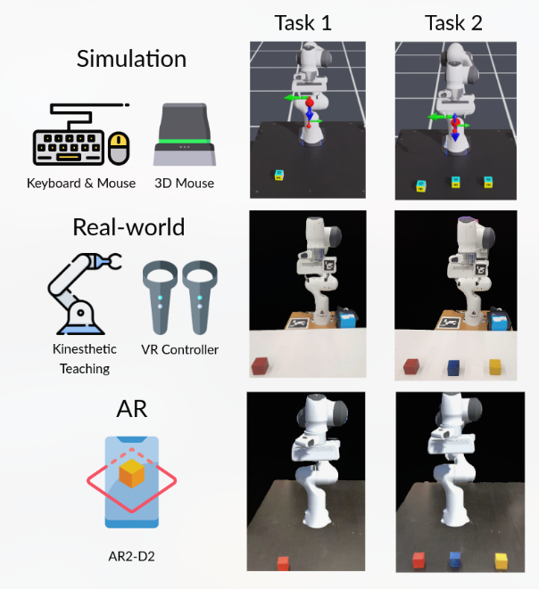
Human-robot interaction for robotic manipulator programming in Mixed Reality
和我毕设很像的工作,居然已经发ICRA了?
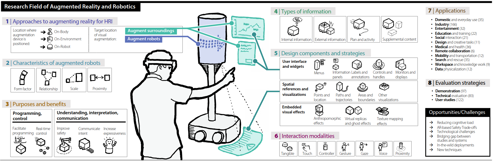
虽然近些年有关AR在人机交互方面应用的研究有很多,但是这些研究大都缺少系统性的分析

Blog Template For New Hexo User
/Pasted_image_20241027192407.png)
本地增添博客内容(markdown文件)->hexo根据文件内容生成网页源码->上通过指令上传(push)到github->github自行部署静态页面
联邦学习(Federated Learning, FL)作为一种新兴的分布式机器学习方法,已经引起了大量研究的关注。要系统地理解联邦学习的相关研究,建议遵循以下结构化的阅读图谱,以便逐步加深对其原理、应用和挑战的理解。
1. 基础与概念性论文
这些论文介绍了联邦学习的基本概念、目标、以及经典算法,是了解联邦学习的起点。
Konečnỳ, J., et al. (2016). “Federated Learning: Strategies for Improving Communication Efficiency” arXiv
- 介绍了联邦学习的概念,提出了最早期的算法(如FedAvg),并讨论了如何优化通信效率。
McMahan, H. B., et al. (2017). “Communication-Efficient Learning of Deep Networks from Decentralized Data” arXiv
- 这篇论文提出了经典的Federated Averaging (FedAvg) 算法,系统阐述了在分布式环境下训练深度学习模型时的通信效率问题。
Yang, Q., Liu, Y., Cheng, Y., Kang, Y., Chen, T., & Yu, H. (2019). “Federated Learning” ACM Transactions on Intelligent Systems and Technology (TIST)
- 详细综述了联邦学习的基本框架、挑战、技术和应用,适合作为综述性的阅读材料。
2. 隐私保护与安全性
联邦学习的一个重要目标是确保数据的隐私和安全,这一领域的研究为其提供了理论基础和技术手段。
Bonawitz, K., et al. (2017). “Practical Secure Aggregation for Federated Learning on User-Held Data” arXiv
- 讨论了如何在联邦学习中实现安全聚合(Secure Aggregation),即确保服务器无法知道单个客户端的模型更新内容,以保护用户隐私。
Geyer, R. C., Klein, T., & Nabi, M. (2017). “Differentially Private Federated Learning: A Client Level Perspective” arXiv
- 探讨了如何将差分隐私(Differential Privacy)应用于联邦学习中,以确保用户模型更新时的隐私。
Zhao, Y., et al. (2018). “Federated Learning with Non-IID Data” arXiv
- 讨论了在非独立同分布(non-IID)数据的情况下,如何在联邦学习中实现模型训练,这是实际应用中的重要挑战之一。
3. 优化与效率
联邦学习中的通信和计算效率问题是该领域的关键研究方向,许多研究尝试通过各种方法优化模型训练过程中的资源消耗。
Li, X., et al. (2020). “Federated Optimization in Heterogeneous Networks” arXiv
- 讨论了在客户端计算能力和网络资源异质性情况下如何进行联邦优化。
Kairouz, P., et al. (2021). “Advances and Open Problems in Federated Learning” arXiv
- 这篇论文对联邦学习的现状、挑战以及未来的研究方向进行了系统性综述,覆盖了通信效率、模型性能、隐私保护等多个方面。
Chen, M., et al. (2020). “Joint Learning and Communication Optimization for Federated Learning over Wireless Networks” arXiv
- 探讨了如何在无线网络环境下优化联邦学习中的学习效率和通信效率。
4. 系统实现与工具
要更好地理解联邦学习在实际中的应用和系统架构,可以参考一些开源框架和实际实现案例。
Google AI. “Federated Learning for Mobile Keyboard Prediction” Blog Post
- 这是联邦学习最早的实际应用之一,讲述了Google如何使用联邦学习提升手机键盘的预测能力。
TensorFlow Federated (TFF): GitHub
- TensorFlow Federated是Google推出的一个开源框架,用于实现联邦学习的系统实验。通过阅读其文档,可以深入理解联邦学习的具体实现细节。
5. 联邦学习在各领域的应用
联邦学习在诸多行业中都具有广泛的应用,了解这些应用有助于扩展对联邦学习实际意义的认识。
Rieke, N., et al. (2020). “The Future of Digital Health with Federated Learning” arXiv
- 探讨了联邦学习在医疗健康领域的应用,特别是在跨医院数据无法集中共享的情况下如何训练模型。
Hard, A., et al. (2019). “Federated Learning for Mobile Keyboard Prediction” arXiv
- 描述了联邦学习在智能手机上如何用于改善键盘输入的预测性能。
6. 联邦学习的挑战与未来研究方向
对于未来的研究,联邦学习还面临许多挑战,比如系统异质性、模型性能与隐私保护的平衡等。
- Wang, J., et al. (2021). “Federated Learning: Challenges, Methods, and Future Directions” arXiv
- 这篇论文对联邦学习面临的主要挑战进行了分析,如数据不均衡、通信成本、模型性能等,并提出了一些未来的研究方向。
联邦学习论文阅读图谱总结:
- 基础理论:先了解联邦学习的基本框架和经典算法。
- 隐私与安全:深入研究数据隐私保护和安全机制。
- 优化与效率:关注如何优化联邦学习中的通信与计算。
- 系统实现:通过工具和实际案例理解系统实现细节。
- 应用领域:了解联邦学习在不同领域的实际应用。
- 挑战与未来方向:展望联邦学习的未来挑战和潜在研究方向。
通过这个图谱,你可以系统地了解联邦学习的关键领域,并逐步深入到各个具体问题的解决方法与研究前沿。

Godot Editor
- Basic https://www.youtube.com/watch?v=q7wlSvt0JIc&list=PL4cUxeGkcC9iHCXBpxbdsOByZ55Ez4bgF
- UI https://www.youtube.com/watch?v=RHcHMRUGDHU
- UI doc https://docs.godotengine.org/en/stable/tutorials/ui/index.html
- UI theme
- performance https://www.youtube.com/watch?v=q1nwCJpjURQ
GDscript
- Basic https://www.youtube.com/watch?v=e1zJS31tr88
- Simplify https://www.youtube.com/watch?v=74y6zWZfQKk
- doc https://docs.godotengine.org/en/stable/tutorials/scripting/gdscript/index.html
GD-Shader
- Intro https://www.youtube.com/watch?v=BRPy8n2Ayc8
- doc https://docs.godotengine.org/en/stable/tutorials/shaders/introduction_to_shaders.html
- hand draw https://www.youtube.com/watch?v=4dfADUfyKTA&t=10s
- water wave
- toon shader
- Course https://github.com/gdquest-demos/godot-shaders?tab=readme-ov-file